Creating 2D symbols for P&ID
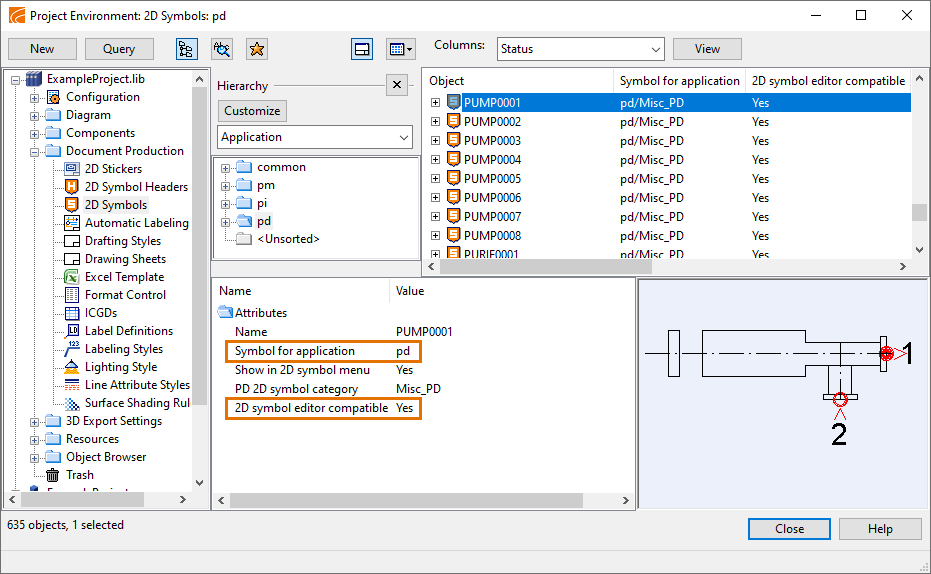
In the Project Environment dialog, in Document Production > 2D Symbols, you can use the CADMATIC 2D Symbol Editor application to create or edit 2D symbols used by the CADMATIC P&ID application.
The CADMATIC 2D Symbol Editor opens when you select to create or edit a 2D symbol and the symbol has the following attributes:
- Symbol for application = pd
- 2D symbol editor compatible = Yes
We recommend that you follow these guidelines when creating or editing 2D symbols.
Define grid size
At the start of a project, the project administrator should decide the preferable grid size of P&I diagrams. The spacing of the grid and the size of the 2D symbols should be such that when a 2D symbol is snapped to the grid, the sides of the symbol align with the grid lines. This allows the diagram documents to have a clean, consistent look that is easy to read.
Symbol size is usually defined in the standard. For example, in the ISO standard the graphical symbols are shown in a grid where the spacing (module size) is M=2.5 mm. When using that kind of grid, then for example the length of a valve symbol could be 5 mm. If P&I diagrams need to be very densely populated, then it can be decided that valves are drawn at half size.
In the CADMATIC 2D Symbol Editor and CADMATIC P&ID, the user can define the grid properties, show or hide the grid, and select whether objects should snap to the grid.
Defining the grid in 2D Symbol Editor
In the CADMATIC 2D Symbol Editor application, you can edit the grid settings by selecting the Home tab > Grid group > Settings.

The Options dialog opens, displaying the Grid tab.
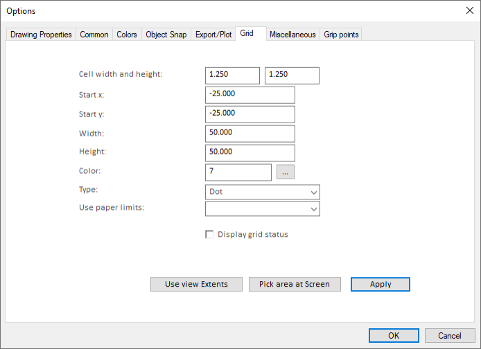
Tip: It is often beneficial to use a grid size that is divisible with the main grid size—for example 1.250 or 0.625.
When designing a symbol, you can press F7 to show or hide the grid. See Grid.
Defining the grid in P&ID
In the CADMATIC P&ID application, you can edit the grid settings by pressing F10. The Grid & Snap Settings dialog opens.
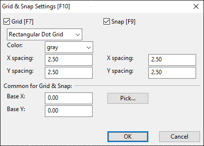
You can press F7 to show or hide the grid. You can press F9 to enable or disable snapping to the grid.
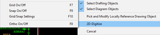
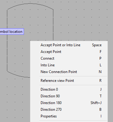
The grid commands can also be performed from the 2D-Digitize context menu:
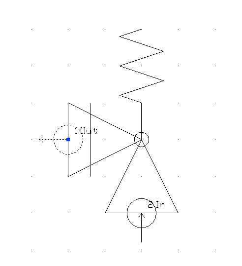
Define insertion point
In the CADMATIC 2D Symbol Editor application, the zero point of the drawing area designates the insertion point (snap point) that will be used when a diagram designer is inserting the object template into a diagram.
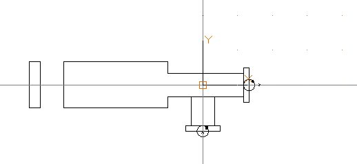
As a general guideline, we recommend symbols to be designed so that the zero point is in the middle of the object. For example, if vessel's width is 15.0 mm and grid size is 2.5 mm, the vessel's middle point at 7.5 mm can be snapped to a grid point to make the vessel's sides align with the grid.
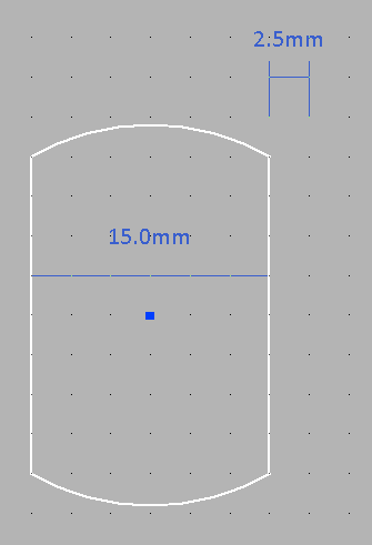
The snapping can also be set to one-half of the grid spacing. If vessel's width is 7.5 mm and grid size is 2.5 mm, the vessel's middle point at 3.75 mm can be snapped to one-half of the grid spacing to make the sides align with the grid.
The insertion point also defines how the object is rotated when inserted for the first time.
Define nodes
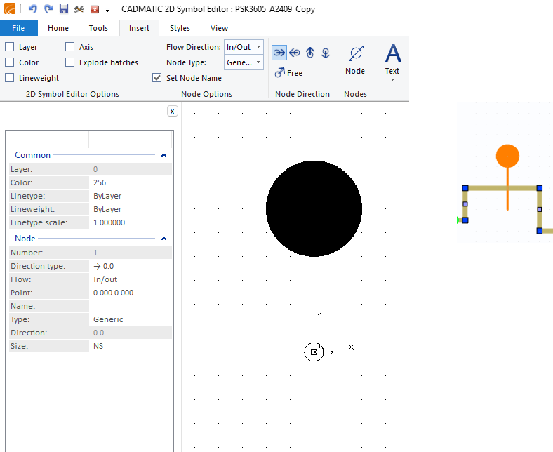
In the CADMATIC 2D Symbol Editor application, add a node to each connection point of the 2D symbol. The selected Node Options and Node Direction are applied to the nodes you add with the Node tool.

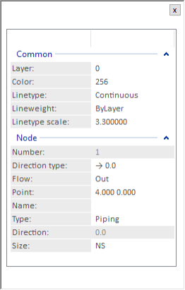
You can view and edit the properties of the inserted nodes in the property panel:
-
Number (read-only) – The node number.
When you insert nodes, the first node is node number 1, the second node is number 2, and so on.
If valve symbols have nodes that relate to different nominal sizes, the nominal sizes are defined in the database card, and your site uses a consistent system where for example the first node always has the biggest nominal size, add the nodes in the required order.
-
Direction type – The direction in which the connection line is drawn from the node: 0, 90, 180, 270, or Free.
-
Flow – The flow direction: In/Out, In, or Out.
-
Point – The node's coordinates.
-
Name – Naming the nodes is optional, but we recommend that you name them to recognize the nodes more easily and to enable node mapping (see Mapping nodes between P&I diagram and the 3D model).
In node name you can only use uppercase and lowercase letters, numbers, and the underscore "_" character.
-
Type – Node type can be set to:
- Generic – The default type for nodes created before node type started to be supported.
- Piping – If selected, only pipelines can be connected to the node.
- Instrument – If selected, only instrument lines can be connected to the node.
- Electric – If selected, only electrical lines can be connected to the node.
Note: Setting the appropriate node type becomes important when the piping network is released to 3D design and there are, for example, two-way valves that have an instrument connection. If at least the instrument node is correctly marked, the valve will not be mistaken as a three-way valve.
-
Direction (read-only) – The angle of the connection line.
-
Size – The nominal size identifier of the node: NS–NS9.
For example, in the symbol of a reducer, you can define which node uses NS and which uses NS2.
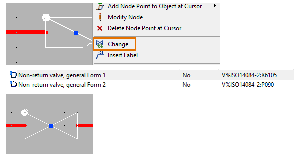
In CADMATIC P&ID, you can change the node properties of a diagram object as described in Modify.
Placing nodes in the 2D symbol
When adding nodes to a 2D symbol, snap the nodes to the grid. Make sure that the grid size is such that the nodes will hit the grid/snap points in the P&I diagrams.
If the symbol is for an inline object, it may only require a single node. When inserted into a piperun, the symbol does not cause the piperun to be cut, but still moves along if the piperun is moved.
Defining nominal sizes in the 2D symbol
When the design project uses piping components that connect pipes of different sizes, the nominal size of each connection can be defined already in the 2D symbol.
For example, in the 2D symbol of a reducer, you can specify the two different nominal sizes that the object template can bring to the P&I diagram object.
Be consistent in how you assign nodes to 2D symbols and define their nominal sizes in a project. For example, always use node number 1 for the bigger nominal size and node number 2 for the smaller. When it is known that component has more than one nominal size, it is important to define NS already in the 2D symbol. This is because the consistency check will notify the diagram designer of error if the nodes are not marked correctly. Also, the Diagram Piping Network that is created to 3D will be erroneous and the topology report will report errors if the nodes do not have correct nominal sizes (the error "NS100 should be 100" is one of these) and node types.
Editing 2D symbols that are already in use
When a 2D symbol has already been used in diagram documents and you want to edit it, consider the following:
- Do not change the name of a 2D symbol that is already in use.
- Avoid changing the node point locations of a 2D symbol that is in use. If you do change them, all affected diagram symbols and their connections to lines need to be manually relocated with the command Home > Move.
- You can change the node name, node direction, flow direction, and nominal size also when the 2D symbol is in use. However, these changes are not automatically applied to the existing diagram objects. To update an existing diagram object, you can use the command Home > Move to redraw the symbol.
Changing the object template of multiple diagram objects
When designing a P&I diagram, the user can select multiple similar objects and change their object template. For example, when a number of valves use the same sub-table, have the same size, and their node points match, the user can change the valve object template to another template. This is only possible when the 2D symbols have their insertion point and node points in exactly the same location.
Create custom 2D symbols in diagrams
In the CADMATIC P&ID application, object templates whose name starts with Create can be used to create diagram objects without a predefined 2D symbol. This enables the designer to freely create the look of a special symbol, such as a conveyor.
These diagram object templates have a special context menu. You can, for example, use standard Ctrl-C and Ctrl-V commands to copy–paste drafting lines from a DWG document opened in CADMATIC Viewer to the active diagram, and then use the context-menu command Assign/Unassign to symbol group to assign the drafting lines from the drawing view to the diagram symbol. The original copy will then be removed, and the user-created custom object works just like any other diagram object, except in this case also the symbol lines can be edited later.
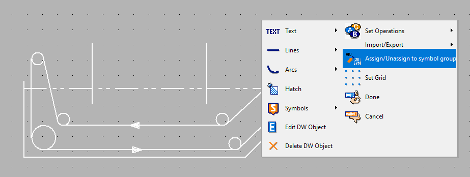
Note: When creating a custom object in this way, the diagram designer must create all the required connection nodes.
Manage diagram object templates
When creating object templates for P&I diagrams, create the commonly used templates in the library. The more special templates you can create in the projects where they are needed.
CADMATIC P&ID application's object template combines the 2D symbol, object type (main table such as EQUIPMENTS), and object subtype (sub-table such as PUMPS). The main table and sub-table define the object attributes in the SQL database. If the user needs to be able to change the object while drawing the diagram, also the main table and sub-tables need to match.
It is not possible to change the object type (main table category) of the object template.
It is not recommended to change the object sub-table if the objects are already in use in diagram documents. If the sub-table is changed, the change will only be applied to new objects. The objects that have previously used this object template will continue to reference the previous sub-table. If the sub-table is no longer available, the object template does not work.
From a live project, it is not possible to delete a sub-table that is referenced in the SQL database. If an object template is imported from another project and refers to a sub-table that does not exist in the new project, the administrator needs to manually set the correct sub-table.
If a diagram object in a P&I diagram document is imported from another project and the sub-table does not match, the imported object will not work and is automatically removed in the import. See Objects from/to file.
The 2D symbol that the object template uses can be changed, but the objects that have already been placed in diagrams will refer to the old symbol. If the old symbol is not available anymore, the symbol will be empty when the user opens a diagram that has used this symbol, and the log will contain a warning such as:
Warning: Symbol Angle_safety_valve_spring not found
This kind of object can be removed from the diagram, if appropriate. If a symbol with the same name is created again or assigned to the project, the program will automatically use that.